Source: http://www.youtube.com/watch?v=Q5Al5ME2HfE&feature=relmfu
 |
| Got it, 20mm wide bar stock! |
That's where things fall apart, quickly.
-Sketchup to the Rescue (kinda)!-
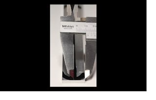
So, it was back to the video for another close look and a determination of the path forward (and another screen capture).Ah, nice collection of all sorts of goodies to look at and glean information. There's my little bar in the middle, all nicely machined and polished and with the one known dimension of 20mm from the markup image above, that was all I needed. One quick visit to Google, a download of Sketchup, and some searching about images, I was able to learn how to import images to the background and scale them to fit a known dimension. All is right with the world.
Click on the image here, and you'll notice the bar stock in the Sketchup image as close as I could get it to measuring 20mm in width and a couple other dimensions on the tube stock that show it being close to 5.8mm in diameter - which is roughly 1/4 inch. That seemed reasonable, so it was off to measure the rest of the parts by drawing polygons over each piece and getting a rough dimension. Once that was done, it was off to Home Depot (HD) to start getting a few pieces of flat bar stock and tube stock and get to cutting! I started with the tube stock, cutting the rough length from the 36" long stock and bending it once to 90° about 55mm from the end and once more at 45° about 160mm from the completion of the first 90° bend. Following that, a bend of the second tube, a little straightening, and I was feeling good. Yup, this time Sunday afternoon, I'd be chasing the kids around the yard or the basketball hoop in the driveway doing some test shots.
Tube bending was not a problem at all. Quarter inch aluminum bends quite readily with the proper tube bender (also available at HD, plumbing department). Two tubes bent with 45 and 90 degree bends, first problem. These two bends have to be done parallel to each other, that is, when placed on a flat surface, the tubes should lie flat to the surface and should be matching each other as far as location of the bends. The location isn't the hard part, it's the parallel bending that's the problem. Still haven't figured out how to do this with a simple tube bender and doing it handheld. With the 1/4 inch tube, getting the tubes straight and parallel is easy due to the thinness of the product.
Tubes bent, now on to the spacer plates that keep the tubes separated. Using image here showing the lower balancing mechanism, we can see the plate that keeps the tubes separated. There is a matching platform at the top of the tubes, as well as the platform that the camera mounts on, that maintains the look uniformly from top to bottom. Back in Sketchup, the drawing dimensions showed a roughly 32mm x 32mm (1.25in. x 1.25in) square - measured, cut, done. Drill through holes in the corners, in an aesthetically and mechanically pleasing location, viola! I choose to create 4mm holes, they were easy to work with, I found a metric tap and die set at HD and the scale seemed right. Hold on, 4mm holes are going to be tough to drill through 1/4inch (~6mm) wide tubing, isn't it? Oh yeah, down right impossible without a drill press and don't even mention trying to tap that hole so the plate can be mounted to the tube. Even a through hole and using nuts and bolts to hold the plate on is going to be very tough.
It would appear that 1/4 inch tubing is not the correct choice for this project afterall.
- Next attempt -
Referencing the image just above, a second attempt was made to determine correct part sizing. Hmm, what's that I see on there, is that a measured scale? Yeah, sure is! Assuming this is scaled in centimeters on the major markings, I determined that the sliding bar was about 3cm wide which translates to about one inch. Oh, happy day, it just so happens that HD sells 1 inch wide aluminum bar stock. Also, it would appear that the weight slider is around 17cm long, close to 6-7 inches. The track pieces that hold the slider in place are close to 0.5 inches and there are two of them, so the bottom plate is 0.5+0.5+1 inch tall = 2 inches. Again, HD to the rescue, they carry 2 inch bar stock as well. Super. Back to our parts image, we can now start making some more informed decisions about part sizes. The curved weight bar is going to be 6in. X 1in. The other two pieces of long, flat bar stock (which make up the camera platform) are going to be the same size. The short bar stock with 3 holes, again 1 inch wide and width will be the same as the square plates. The square plates will be 2 inches high, with an indeterminate width (at this time!). And the tube stock turns out to be 3/8in. diameter in the final analysis. This, along with the assorted 4mm machine screws and 1/4x20 threaded stock should get me started on the best path for success.
- Back to Sketchup -
 |
| Click pic to embiggen |
 You may have noticed, that I didn't include width dimension in some of the parts in the last section. That's because I can't determine it from the video screencaps below. You'll notice this image, with the rotated balance bar, which we know to be 1 inch wide, would appear to be able to just fit between the support bars. Knowing that those are 3/8inch diameter pieces, it would show the overall width of the lower support section to be around 1.75 inches.
The lower image shows the overall assembled device, including the upper camera support platform. The sizes there can be estimated from the diameter of the tripod mounting screw and the gap that it creates between the support platform. Given that this screw is 1/4in diameter and we've used 1inch bar stock for the supports, that gives a dimension of 2.25 inches, overall for the top. Since 2.25 inches > 1.75 inches, I couldn't rationalize that difference, so I went off the plan.
Looking over the Sketchup document above, you can see that I went with spacing the whole thing 2 and 5/8 inches from outside to outside. I don't know why I did that, I think it was a mistake in laying out the pieces that I didn't notice until I started assembling the cut pieces. I also think it lends to a wider base onto which the camera can be mounted, thereby creating better support. Had I laid out the drawing correctly, I'd be closer to the overall 2.25 inch width and it would change each part other than the long pieces.
Part two of the build will detail some other things that I found out during assemble and the fact that the handle design can't be re-created because that part can't be found in North America. Until then chew on the Sketchup file and keep building.


